The thermal expansion of stainless steel pipe is predictable yet significant. Austenitic grades like 304/316 grow more than ferritic or duplex. Use mean CTE over the temperature span and calculate movement with ΔL = α·L0·ΔT. Growth affects alignment, anchors, supports, and gasket integrity. Manage with correct guide spacing, expansion loops or offsets, and inspected bellows. Choose joints wisely: welded for integrity, grooved for flexibility, flanged for service. Account for mixed materials and insulation. Installation, commissioning, and monitoring practices complete the picture.
Thermal expansion refers to the tendency of a material to change its shape, area, or volume in response to temperature changes. As temperature increases, the atoms within stainless steel vibrate more intensely, pushing each other slightly farther apart — resulting in measurable elongation.
In practical terms, this means that a stainless steel pipe will lengthen as it heats up and contract as it cools down. The extent of this dimensional change depends on the material’s coefficient of linear thermal expansion, commonly represented by the symbol α (alpha).
The basic formula for calculating linear expansion is:
ΔL = α × L × ΔT
where:
- ΔL = change in length (mm or m)
- α = coefficient of linear expansion (1/°C or µm/m·K)
- L = original length of the material (m)
- ΔT = temperature difference (°C)
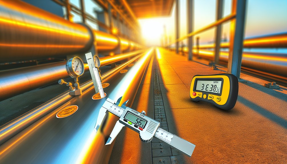
A 100 m long 304 stainless steel pipe exposed to a temperature increase of 150 °C can expand approximately:
ΔL = 17.2 × 10⁻⁶ × 100 × 150 = 0.258 m (≈ 258 mm)
This level of expansion can create considerable stress if not properly accounted for during pipeline layout or support design.
Although stainless steel is prized for strength and corrosion resistance, its dimensional change with temperature can drive critical design outcomes. In pipe systems, small shifts compound over long runs, tightening anchors, stressing welds, and misaligning equipment. Understanding thermal properties enables designers to anticipate expansion effects and set clear movement allowances, rather than react to failures.
Unchecked growth can overload supports, transmit forces to pumps and valves, and compromise gasket integrity. Precision planning specifies guide spacing, flexibility at offsets, and clearance at penetrations to keep loads predictable.
Expansion joints are not the only lever; smart routing, loops, and sliding shoes often deliver quieter, lower-maintenance control. Documentation of expected movement, plus installation verification, turns uncertainty into managed behavior and extends service life under routine temperature cycling.
Because thermal growth scales directly with the material’s coefficient of thermal expansion (CTE), designers must reference values specific to stainless grade and temperature.
Below is a reference chart showing typical coefficients of thermal expansion at room temperature (20–100 °C):
| Material Grade | Thermal Expansion Coefficient (×10⁻⁶ / °C) | Typical Application |
|---|---|---|
| 304 / 304L | 17.2 | Sanitary, food processing, architectural tubing |
| 316 / 316L | 16.5 | Chemical, marine, and heat-resistant systems |
| 430 (Ferritic) | 10.4 | Low-cost decorative panels, indoor fittings |
| Carbon Steel | 12.0 | Structural and mechanical piping |
| Copper | 16.7 | Heat exchangers, plumbing |
| Aluminium | 23.6 | Lightweight components |
Austenitic grades (e.g., 304, 316) generally exhibit higher CTEs than ferritic or duplex stainless steels, a difference that widens with rising temperature. Reliable control begins with coefficients comparison across candidate alloys, using vetted datasets or manufacturer charts tied to defined temperature bands.
Temperature effects are not linear across the entire range; many tables publish mean CTE from ambient to a specified temperature. Selecting a mean CTE appropriate to the expected operating window reduces bias.
For cycling service, CTE should reflect the upper bound to protect against worst-case movement. Mixed-alloy systems demand the highest scrutiny, as differential CTE drives interface stresses and misalignment.
With the coefficient of thermal expansion established, linear movement is computed using ΔL = α·L0·ΔT, where α is the appropriate mean CTE, L0 is the original pipe length, and ΔT is the temperature change. For linear movement calculations, inputs must use consistent units and a temperature interval that reflects actual operating swings. Thermal strain analysis follows directly: ε = ΔL/L0 = α·ΔT. This dimensionless strain quantifies proportional elongation and enables tidy comparisons across sizes.
| Parameter | Definition |
|---|---|
| α (CTE) | Mean coefficient over ΔT |
| L0 | Original pipe length |
| ΔT | Operating temperature change |
Thermal growth can shift pipe runs enough to cause misalignment of flanges and nozzles if expansion is not accommodated. Implementing preventive maintenance that includes regular inspections of supports and seals helps catch early signs of stress, leaks, and loosened fittings caused by thermal movement. Selecting materials and designs that comply with ASTM standards helps ensure appropriate thermal performance, corrosion resistance, and mechanical integrity under expected operating ranges. Selecting tube grades such as 316 stainless can improve resistance to chloride-induced corrosion and maintain reliability in marine or chemical environments. ASTM specifications like ASTM A312 define material requirements and testing for austenitic stainless steel piping used in high-temperature and corrosive service, supporting consistent performance and safety.
As the pipe expands or contracts, loads redistribute to guides, shoes, and anchors, potentially exceeding allowable reactions.
These movements also induce thermal stresses at fixed points and restraints, making support selection and anchor placement critical to reliability.
In corrosive environments, accounting for chloride exposure is essential, as corrosion can weaken supports and anchors, increasing the risk of misalignment and failure over time.
Misalignment from thermal growth arises when stainless steel pipe heats and lengthens unevenly, shifting flange faces, skewing supports, and imposing unintended loads on connected equipment.
The primary misalignment causes include temperature gradients along runs, asymmetric insulation, restrained branches, and differential coefficients across mixed alloys or components.
These thermal growth effects rotate flanges out of parallel, introduce bolt bending, and degrade gasket seating, escalating leakage risk and assembly torque demand.
Small angular deviations propagate through spools, concentrating stress at nozzles and welded attachments.
Elbows magnify offsets by converting axial expansion into lateral displacement.
Cold-set alignment achieved during installation can disappear at operating temperature, creating hidden preload and vibration excitation.
Controlled outcomes require predictable growth paths, quantified clearances, and verified cold alignment targets that reflect actual operating temperatures and shutdown cycles.
As growth-induced offsets accumulate, the pipe–support system becomes the arbiter of where forces and moments land. Anchors, guides, and shoes determine whether thermal strain translates into bending, thrust, or controlled sliding. In pressure and sanitary services, selecting materials and tolerances per ASTM A312 and related standards improves predictability of thermal movement and support reactions. For stainless piping in hygienic and high-spec services, pairing proper supports with back purge welding minimizes contamination risks at restraints and preserves weld integrity under thermal cycling. As part of specification, confirming tube OD tolerances and wall thickness tolerances per ASTM A249 helps ensure support fit-up and load predictions remain accurate across manufacturing variations. Quality inspection at each manufacturing stage and final product testing help ensure compliance standards that keep support fit and load predictions consistent across batches.
Where anchors are rigid, forces concentrate; where guides are permissive, alignment is preserved but axial travel increases.
Support loads must be predicted, not assumed. Load ratings govern selection of clamps, springs, and hangers; overrating invites stiffness that traps expansion, underrating risks creep and slippage. In thermal design, specifying OD, WT, and length per ASTM standards ensures supports are sized correctly for combined expansion and pressure-induced loads.
Support materials matter: low-friction pads reduce side load, while high-durometer inserts elevate local stress. Anchor bolts, baseplates, and grout require verified capacity under combined thermal and weight effects.
Strategic gaps, stop limits, and spring cans distribute movement, protecting elbows and branch connections while keeping flanges within allowable misalignment.
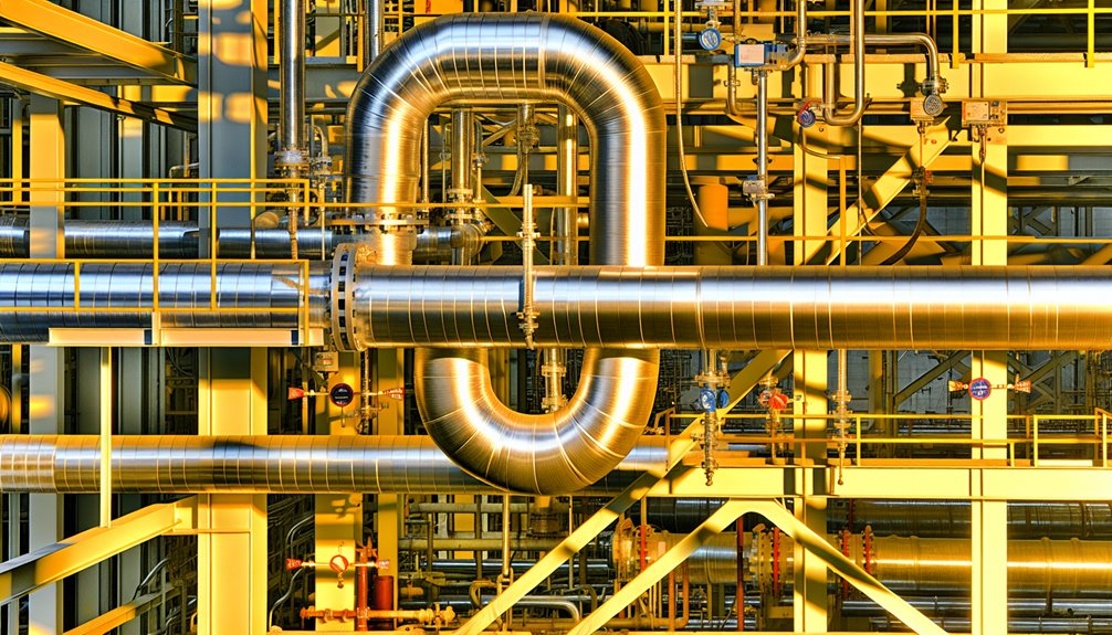
While stainless steel piping inevitably expands and contracts with temperature changes, the method chosen to absorb that movement depends on layout, loads, and service conditions. Expansion loops maximize thermal flexibility using standard elbows; they suit long straight runs where space exists and pressure drop tolerance is acceptable. Offsets redirect movement around obstacles, trading modest added friction for compact routing. Bellows-type expansion joints deliver high stroke in tight footprints but demand precise alignment, restraint of pressure thrust, and vigilant inspection. In many engineered systems, selecting components that meet ASTM standards ensures consistent mechanical and corrosion performance across loops, offsets, and bellows. In corrosive or marine services, choosing 316 or 316L stainless steel helps resist pitting and crevice attack while maintaining weld integrity. For demanding environments like marine and chemical processing, sourcing tubing from reputable 316 stainless steel tube factories helps ensure compliance with ASTM A312/A269 and reliable corrosion resistance. When specifying materials, verify conformance with ASTM A270 to meet sanitary and industrial quality benchmarks.
- Stainless steel’s high melting point and corrosion resistance support reliable performance of loops, offsets, and bellows across demanding service conditions.
| Option | Strength | Use-When |
|---|---|---|
| Loops | High flexibility | Space available |
| Offsets | Route around constraints | Moderate movement |
| Bellows | Compact, large stroke | Tight spaces |
Selection hinges on displacement magnitude, available envelope, cyclic frequency, media compatibility, and maintenance philosophy. Controlled movement prevents fatigue, leakage, and downtime.
Effective control of thermal growth begins with an anchor placement strategy that fixes movement at deliberate points and directs expansion toward flexibility features.
Guide spacing rules then limit lateral drift and buckling, keeping axial movement predictable between restraints.
Finally, support load distribution guarantees reactions are shared appropriately, preventing overstress at concentrated locations.
Two decisions govern anchor placement in stainless steel piping: where to fix movement and how to control the remaining thermal growth. The primary anchor is positioned to lock a known reference point—often near equipment nozzles—to limit load transfer into sensitive flanges.
Secondary anchors are then located to segment runs so each section expands toward designed flexibility elements.
Anchor types are selected for predictable restraint: fixed anchors for zero axial slip, limit anchors to cap movement, and directional stops to block targeted axes.
Installation techniques emphasize rigidity and alignment: full-penetration weldments or bolted shoes on reinforced steel, grout-filled bases, and verified torque to eliminate creep.
Thermal travel is mapped from anchors to expansion loops or joints. Anchor-substrate capacity, corrosion isolation, and inspection access are planned from the outset.
With anchors establishing fixed reference points and expansion paths, guide spacing governs how the pipe stays aligned as it grows.
Effective practice sets the first guide close to the anchor to prevent lateral kick, then spaces subsequent guides at intervals derived from diameter, wall thickness, temperature range, and allowable offset.
Tighter spacing is used near expansion joints to prevent buckling and to guarantee axial movement stays centered. Guides must clear pipe insulation and allow for inspection.
Misalignment risks seal wear, joint overtravel, and clamp fretting. Uniform guide rigidity and low-friction shoes maintain predictable movement.
Elbows require reduced spacing to control out-of-plane bending. Documented calculations, field verification of straightness, and setting cold gaps per design tolerances give the engineer predictable thermal behavior.
A balanced support load distribution guarantees thermal growth forces are shared predictably between anchors, guides, and intermediate supports. Effective control begins with fixed anchors that define zero-growth points and set reaction paths.
Guides then channel movement axially, preventing lateral drift and reducing bending moments. Hangers and shoes share gravity loads while allowing calculated axial slip.
Engineers apply load balancing by segmenting the line between anchors and placing guides at intervals that match thermal movement profiles and allowable stresses. Support spacing is tuned to limit span deflection and clamp friction, preventing unintended load transfer to equipment nozzles.
Expansion joints or loops are positioned so reactions remain within design limits. Verification uses spring-rate data, friction coefficients, and restraint stiffness to reconcile predicted loads with field adjustability and monitoring.
Although the pipe material dictates overall behavior, joint selection largely determines how thermal expansion is accommodated and where stresses concentrate.
Welded joints offer maximum joint integrity and leak-tight performance but minimal joint flexibility; they transmit thermal stress directly into the pipe and anchors. In critical services, aligning joint selection with ASME B31.3 helps ensure thermal movements are safely managed without exceeding code-allowable stresses. In sanitary systems, weld quality must meet ASME BPE expectations to maintain smooth, crevice-free surfaces that minimize microbial risk. For thin-walled tubing, TIG welding provides precise heat control that helps limit distortion and preserves surface finish in hygienic services. Regular six-month inspections help verify joint integrity and catch early signs of corrosion or misalignment.
Welded joints maximize integrity and leak-tightness but offer minimal flexibility, transmitting thermal stress into pipe and anchors.
Flanged joints introduce disassembly capability and controlled gasket compression; bolt torque and gasket selection influence movement tolerance and corrosion resistance.
Grooved connections provide the greatest joint flexibility through controlled end separation and angular deflection, reducing thermal stress and easing alignment.
Installation techniques govern outcomes: weld procedures must limit heat input and distortion; flange bolting requires calibrated torque and re-tightening protocols; grooved couplings need verified groove dimensions and bolt seating.
Material compatibility, surface finishes, and protective coatings further preserve corrosion resistance and long-term reliability.
When joints are welded, proper shielding gas selection and current settings—such as argon or argon-helium mixtures for GTAW—help control heat input and preserve corrosion resistance.
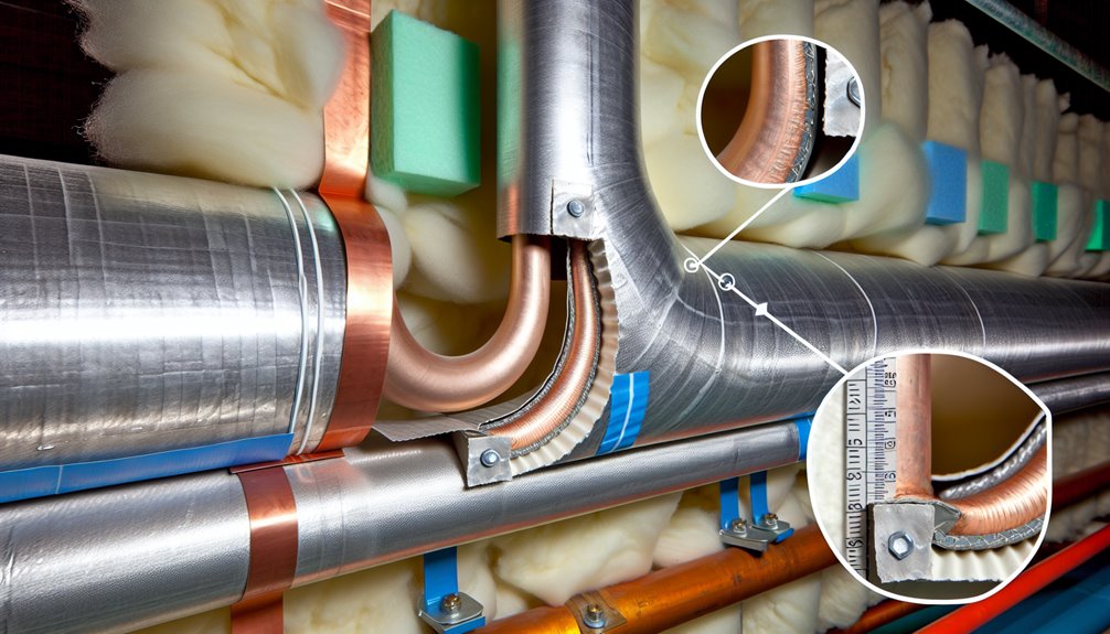
Because stainless steel systems often interface with dissimilar metals and layered insulation, differential thermal expansion emerges as a primary source of stress, misalignment, and seal degradation.
Mixed materials—such as stainless, carbon steel, copper, and aluminum—expand at different rates, while insulation materials add temperature gradients that intensify axial growth and bending.
Differential slip at supports, clamps, and penetrations concentrates loads where compliance is limited. Gasketed joints and instrument connections are especially sensitive to shear generated by restrained movement.
Precision requires explicit allowance for relative movement and thermal lag across the pipe wall and jacket.
1) Quantify coefficients and temperature profiles for mixed materials and insulation materials to calculate relative displacement.
2) Define controlled slip or restraint at supports to prevent forced bending.
3) Select seals and interfaces tolerant of differential shear and cyclic strain.
Additionally, account for how tubes are measured by outside diameter while pipes are measured by inside diameter, since this affects thermal growth calculations and fit-up tolerances at interfaces.
Effective field practice begins with pre-installation site checks that verify alignment, anchor locations, guide spacing, and clearance for movement.
Commissioning then confirms thermal allowances by validating expansion joint settings, hanger loads, and cold-spring targets under controlled heat-up.
Ongoing expansion monitoring uses reference marks, sensor data, and inspection intervals to detect drift, binding, or overstress before they escalate.
Where should a project team begin before a single length of stainless steel pipe is set on supports? With disciplined pre-installation site checks that remove guesswork and protect thermal movement allowances. Teams should also review applicable pipe schedules to ensure wall thickness selections align with pressure, temperature, and flow requirements anticipated during thermal expansion. Additionally, confirm that specified pipe dimensions meet ASME B36.19M tolerances to avoid misalignment and ensure proper fit during installation.
The team verifies site accessibility for delivery routes, rigging paths, and safe staging. It then confirms environmental conditions—ambient temperature ranges, solar exposure, wind, and corrosive agents—to anticipate expansion behavior and select suitable materials, coatings, and insulation.
Structural interfaces are measured to guarantee anchor loads and support spacing align with calculated growth. Teams should also verify that selected stainless steel grades (e.g., 304, 316, 321) comply with relevant ASTM standards to ensure material quality and performance under anticipated thermal cycling.
Commissioning thermal allowances starts with proving that calculated movements occur safely under controlled heat-up. A disciplined team validates anchor loads, guide gaps, and expansion joint presets against the design model before energizing.
Commissioning procedures define stepwise temperature increments, hold points, and acceptance criteria for displacement, force, and alignment. Permanent marks on pipe, supports, and nozzles verify expected travel; laser or dial measurements confirm values within tolerance.
Technicians release temporary restraints in a defined sequence, torque fasteners to specification, and document cold settings. Insulation remains off critical spools until target movements are confirmed.
Relief paths are checked so that thermal allowances do not overdrive supports or connected equipment. Deviations trigger immediate cooldown, root-cause review, and corrective actions before proceeding to full operating temperature.
With initial heat-up validated and baseline movements recorded, attention shifts to tracking thermal behavior over the asset’s life. Ongoing monitoring anchors operational control, verifying that stainless steel pipe expansion remains within engineered allowances. For systems exposed to aggressive environments or moisture ingress, specifying higher-alloy grades like 316 with molybdenum enhances corrosion resistance and preserves long-term measurement accuracy and support integrity. In addition, choosing 316L for its lower carbon content improves weldability and resistance to intergranular corrosion in long-term service. Leading Chinese manufacturers adhere to ASTM standards, supporting consistent tube quality and long-term performance in demanding environments. To ensure compatibility and quality in mechanical tubing, many projects specify compliance with ASTM A554, which defines mechanical properties, dimensions, and surface finish for welded stainless steel tubes.
Operators deploy expansion sensors at critical anchors, guides, and slip joints, correlating displacement with temperature and pressure trends. Data thresholds trigger inspection, isolating drift from settlement, clamp slip, or insulation degradation. Reports feed maintenance planning and recalibration of spring supports or stops to prevent load transfer into equipment nozzles. In parallel, selecting reputable manufacturers of stainless steel tubing supports long-term reliability and performance, as emphasized by the projected growth of the global stainless steel market.
Three recurring pitfalls dominate stainless steel pipe expansion design: underestimating thermal growth, over-restraining the system, and misplacing anchors and guides. These design errors compound into fatigue, gasket leaks, and nozzle overload. Installation pitfalls follow: field-added clamps become unintended anchors; misaligned guides induce bending; and skipped cold-springing elevates stress. A controlled approach prioritizes quantified growth, correct support spacing, and purposeful flexibility. Incorporate qualified welding procedures and post-weld cleaning to minimize corrosion risk from hexavalent chromium exposure and heat-affected sensitivities.
| Mistake | Proven Tip |
|---|---|
| Ignoring ΔL calculations | Size loops and offsets using verified coefficients |
| Over-constraining spans | Use guided supports with low-friction slides |
| Anchor at thermal midpoint | Place anchors at equipment, guide toward loops |
| Skipping cold-springing | Apply 250% preset where analysis justifies |
He favors stress analysis with realistic friction factors, qualified welds on flexible elements, and inspection checklists that verify guide gaps, shoe heights, and anchor weld sizes.
Like a metronome wearing steel thin, thermal cycling cumulatively shortens pipe fatigue life over decades by driving thermal fatigue, accelerating fatigue mechanisms, initiating microcracks, promoting creep-fatigue interaction, and magnifying stress concentrations; vigilant monitoring, controlled ramp rates, and engineered supports preserve durability.
Code requirements mandate quantified displacement capacity, restraint design, and qualification of expansion joints under seismic codes, typically per ASCE 7, IBC, and ASME B31. Test-based certification, anchor flexibility, guided supports, and clearances are required, with documented analyses verifying worst-case multidirectional movements.
Like a tightened drum, cryogenic effects invert expansion behavior: materials contract sharply, clearances shrink, and stiffness rises. He anticipates embrittlement, altered modulus, seal leakage, and support load shifts, enforcing precise allowances, flexible loops, low‑temperature ratings, and monitored thermal cycles for control.
Yes. Heat tracing can markedly change expansion design assumptions by elevating uniform temperature, reducing gradients, and altering anchor loads. Engineers should implement design adjustments: reassess allowable movements, revise loop lengths, update supports, evaluate insulation, and verify control setpoints for predictable behavior.
Soil settlement compounds thermal movement by creating differential restraint, amplifying bending and joint stress. Significantly, 1% ground strain can double axial force. Control demands strain-compatible joints, strategic anchors, flexible loops, continuous monitoring, and settlement-tolerant backfill to maintain alignment and integrity.
In closing, thermal expansion isn’t a footnote—it’s the plot. One refinery learned this when a 100 m run of 304L grew nearly 30 mm during a heat-up, quietly bowing supports like a violin string tightening to pitch. With the right coefficients, loop selection, and joint strategy, that “stringcan be tuned instead of snapped. Design anticipates movement, installation respects it, and monitoring confirms it—turning expansion from a hidden antagonist into a predictable rhythm in stainless systems.